


A&A-Scheduler
The A&A-Scheduler application is designed to work with microcontrollers. A task scheduler designed to control Arduino and other microcontroller platforms using Android devices. Communication with the microcontroller is carried out using a USB UART adapter. A&A-Scheduler automatically recognizes USB UART adapter drivers and attempts to send a request to the microcontroller, waiting for a ready response. After receiving the ready signal, the A&A-Scheduler will send the appropriate commands to the microcontroller according to the planned schedule. A&A-Scheduler runs in the background.
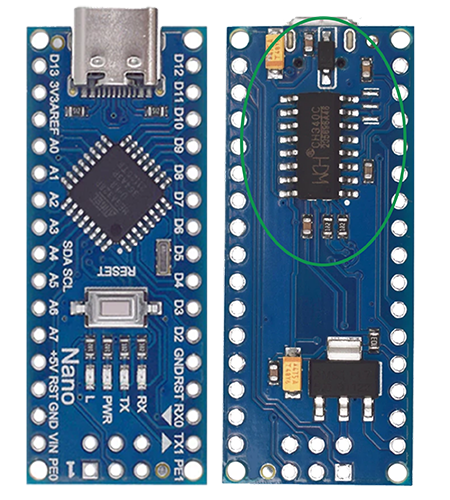
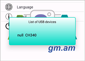
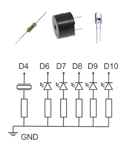

To understand how an application works with a microcontroller, let's look at a simple example. The essence of the example is to demonstrate the recognition by the application of the connection of the microcontroller and the processing by the microcontroller of commands coming from the application. To do this, we will use the Arduino NANO platform, a piezo speaker, 5 (pcs) LEDs, 6 (pcs) resistors. The Arduino NANO platform is already integrated with a USB UART controller and has a USB connector. First of all, let's connect NANO with a USB cable to our android device. When the application is launched or if it is running, the android system will ask us for permission for the application to work with the USB UART. At this stage, it doesn't matter whether you approve or deny this request. Next, go to the control screen and click on the item “List of USB devices”. In the window that opens, you will see a line with the name of the USB UART controller (see figure). The next step is to assemble the circuit shown in the figure and connect it to the corresponding pins of the arduino NANO. You need to download the program to the microcontroller. To do this, we will use the "Arduino IDE".
You can check out the sketch below. After uploading the sketch to arduino NANO, you can connect it to our android device. Power for arduino NANO will come from android device. Now you need to approve the system request to allow the application to work with the USB UART. After that, the note-message icon will change to “v”, and the piezo speaker connected to the arduino NANO will beep. As you can see from the sketch, the application works with the microcontroller at a speed of 115200 bit. When a USB UART controller is detected, the application sends a request - stmA and expects a response in the form - rtmA. After receiving a response, the application considers the connection to the microcontroller established and is ready to send the scheduled commands. Before scheduling a task, you can check how the microcontroller responds to commands. After establishing a connection with the microcontroller on the control screen, select the item “Test commands”. In the list that opens, select the required command. It will immediately be transferred to the microcontroller. For example “Commanda2 = 000011A” means that 000011A will be sent. In our example, this means that two LEDs will light up and turn off after 2 seconds.
Download sketch (here):
const int piezo_pin = 4; void loop() { |